Example: Make and verify the connections
This section discusses using Composer Pro views to make and verify the connections.
Note: This process follows Example: Design and create the project .
In the Connections view, you can:
- Identify Control4 devices to establish a network connection
- Check all network connections
- Define AV connections
- Define control connections
Note: When only one appropriate connection is available in a room for a given connection type, Composer Pro assumes the connection (example: if a TV is the only Audio Output device in a room, the system assumes that the Audio Output connection is routed to the TV). This feature adds value to Composer Pro, but increases the need to verify every connection.
Note: To remove a connection, right-click on the connection and select Disconnect.
To make connections:
- In Composer Pro, click the Connections view.
- Identify the Control4 devices that connect to the controller through the network. Go to each physical device and press the button indicated on the Composer Pro screen.
- Click the Network tab > IP Network.
Notice the devices that do not have an address listed under the Address column.
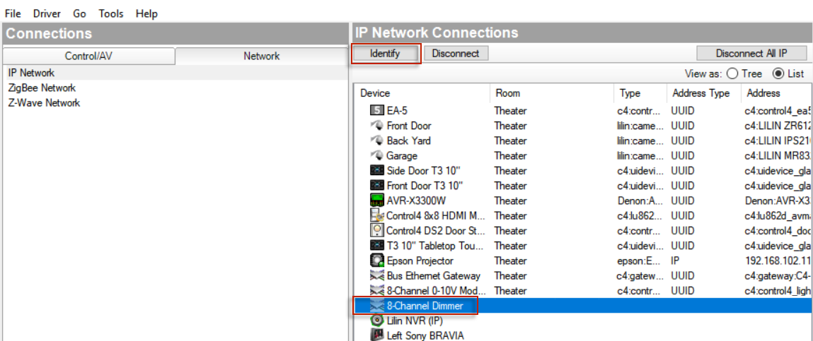
- Select the controller, and then click Identify. The screen to identify the controller appears (in this example, the 8 Channel Dimmer).
- At the physical controller, press the Identification button. This identifies the controller with a unique address in the system. When the address appears on the screen, click Next.
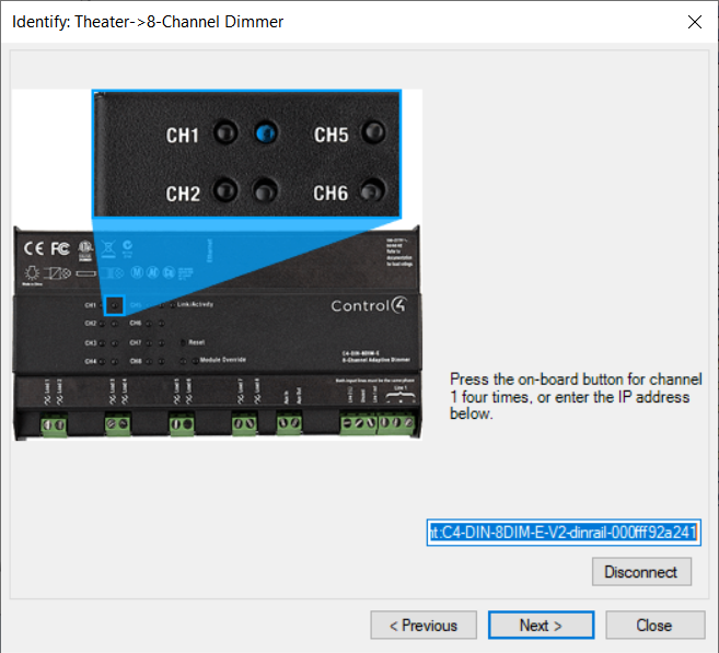
- Select Dimmer, and then click Identify. The screen to identify the dimmer appears. Press the top dimmer button four times. This identifies this specific dimmer with a distinctive address to the system. When the address appears, click Next.

- When the Light Switch identification screen appears, press the top button four times. When the address appears, click Next.
- When the system remote control identification screen appears, holding the physical system remote control press the red 4 button once. When the address appears in the box, click Next to continue.
- If you have a touch screen in your project, press the Enter button on the front of the touch screen. When the address appears in the box, click Next to continue.
- When the Outlet Switch identification screen appears, press the button on the module four times.
- When the 6-Button Keypad identification screen appears, press the top left button four times. When the address appears, click Next.
- When the Dimmer identification screen appears, press the top button four times. When the address appears, click Next.
- When the touch screen identify screen appears, press the indicated button as shown. When the address appears, click Next.
- When the 3-Button Keypad identification screen appears, press the top button four times. When the address appears in the box, click Next.
- When the Control4 Wireless Thermostat identification screen appears, press the middle button four times. When the address appears in the box, click Close to exit Identify mode.
- When you finish identifying the devices, notice that the Address column now has an address for every network device.

- Define the AV and Control connections.
- Video connections (path of video signals)
- Audio connections (path of audio signals)
- Control connections (how the controller communicates with the device)
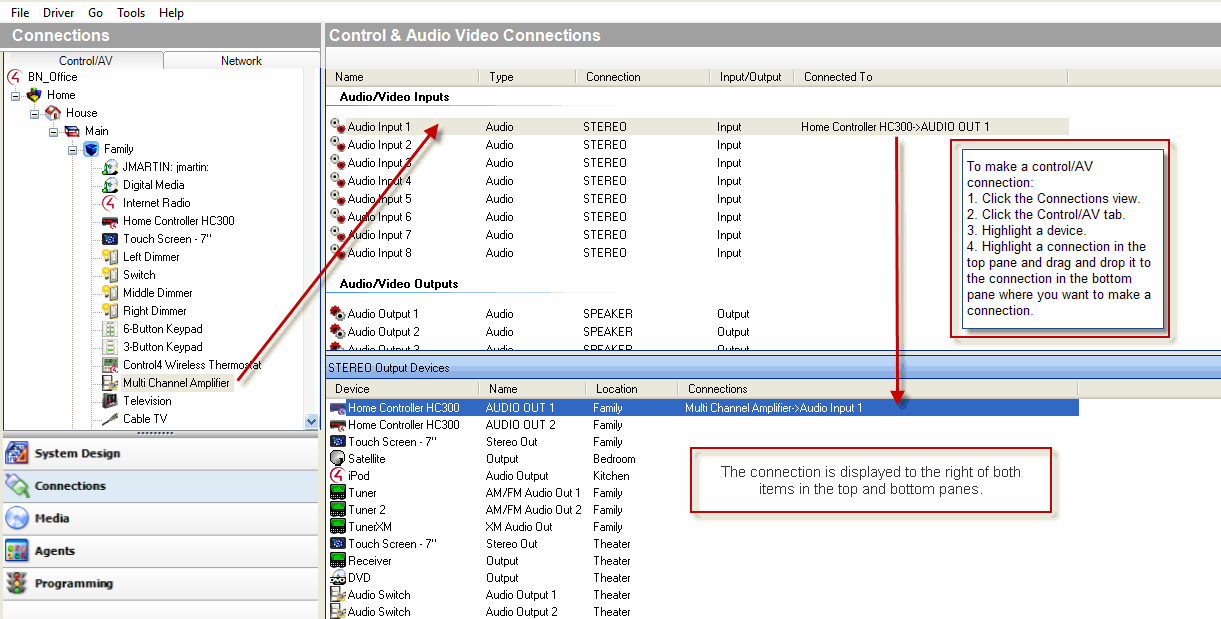
Control and AV connections for a device are visible when you click the Connections view > Control/AV tab, and then select the device. To make a connection between inputs and outputs, from the top pane drag a device’s input (or output) to the output (or input) in the bottom pane.
For each device, define the following when applicable:
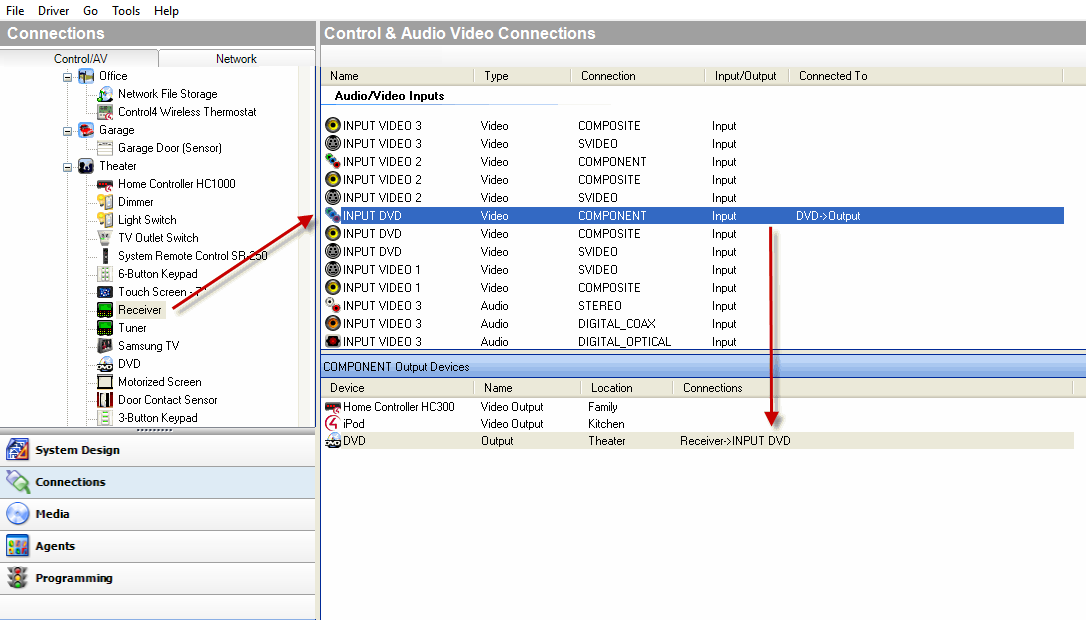
- Define the AV connections for the Receiver.
- Click INPUT DVD (Video-COMPOSITE), and drag it to DVD (Output-Theater) in the bottom pane.
- Click INPUT VIDEO 1 (Video-COMPOSITE), and drag it to Home Controller HC300 (Video Out 1- Family) in the bottom pane. This connects the Receiver Video 1 input to the Controller Video 1 output.
- Click INPUT DVD (Audio-STEREO), and drag to DVD (Output-Theater) in the bottom pane.
Example: In the Connections view under Theater, click Receiver. The right top pane displays all the inputs and output on the back of the Receiver. For Receiver, from the top pane in Audio Video Inputs, make the following connections:
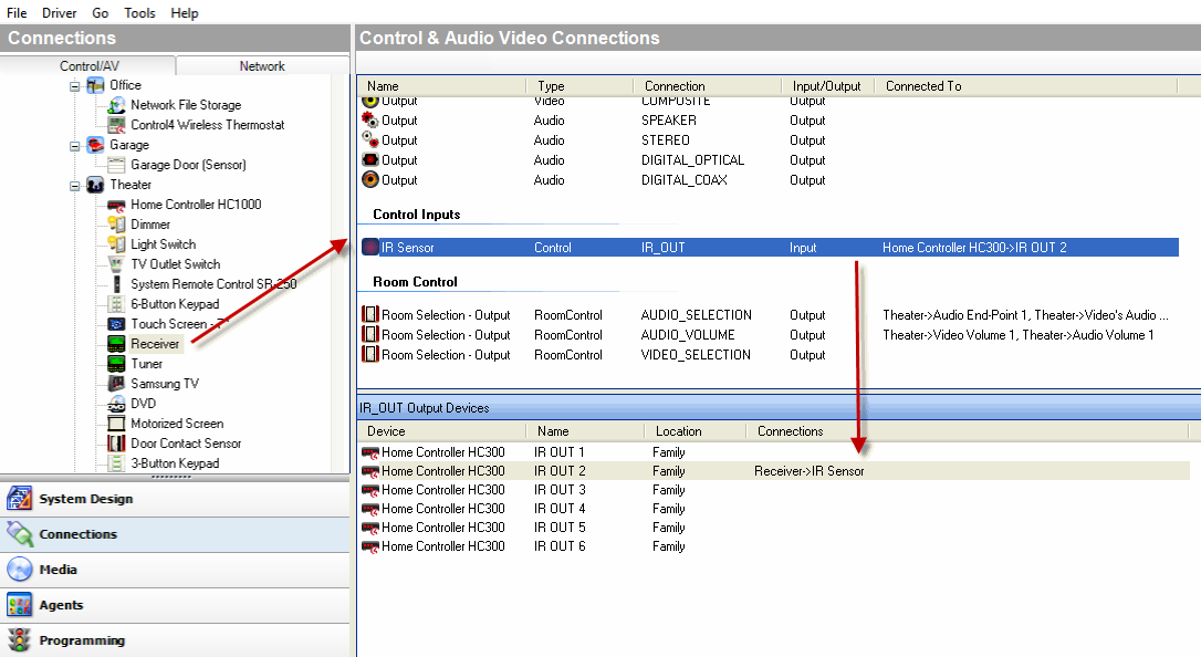
- Define the Control connection for the Receiver to the Controller.
- Click IR Sensor (Control-IR_OUT), and drag it to Controller (IR Output 2-Theater) in the bottom pane.
Example: In the Connections view under Theater, click Receiver. The right top pane displays all the inputs and output on the back of the Receiver.
For Receiver, from the top pane under Control Inputs, make the following connections:
- Define AV and Control connections for the Television.
- Click AV (Video-COMPOSITE), and drag it to Receiver (Output-Theater) in the bottom pane.
- Click AV (Audio-STEREO), and drag it to Receiver (Output -Theater) in the bottom pane.
Example: In the Connections view under Theater, click Television. The right top pane displays all the inputs and outputs on the back of the Television. For Television, from the top pane do the following:
In Audio Video Inputs:
In Control Inputs, click IR Sensor (Control-IR_OUT), and drag it to Controller (IR Output 1—Family) in the bottom pane.
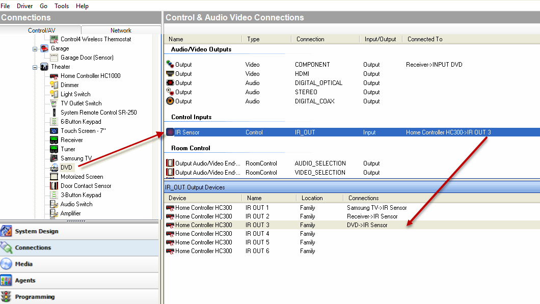
- Define the Control connections for the DVD player to the Controller.
Example: In the Connections view under Theater, click DVD. The right top pane displays all the inputs and outputs on the back of the DVD. From the top pane, do the following:
In Control Inputs, click IR Sensor (Control-IR_OUT) and drag it to Controller (IR Output 3-Family) in the bottom pane.
Tip: If you prefer to set up a video sense loop instead of using a macro, see “Changing power management options.” After you add a video sense loop connection to the DVD player driver, add a control connection between the controller and the DVD player.
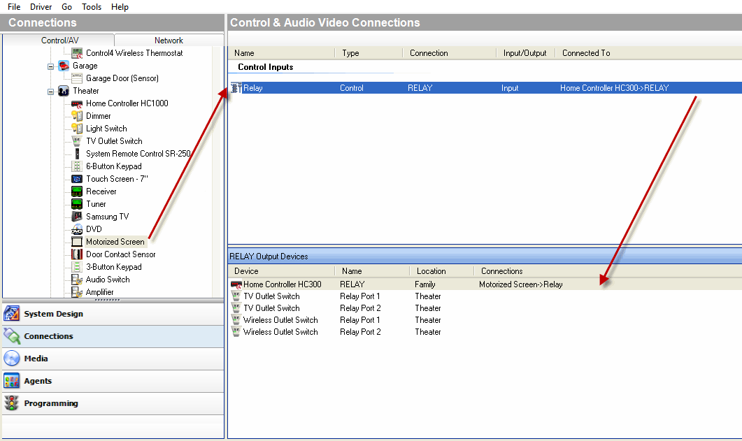
- Define the Control connections for the Motorized Screen to the Controller.
Example: In the Connections view under Theater, click Motorized Screen. The top right pane displays all the inputs and outputs on for the screen.
In the top pane under Control Inputs, click Relay (Control-RELAY), and drag to Controller (Relay Port 3-Family) in the bottom pane.
- Define the Control connections for the Door Contact Sensor to the Controller.
Example: In the Connections view under Theater, click Door Contact Sensor. The top right pane displays all the inputs and outputs for the Door Contact Sensor.
In the top pane under Control Inputs, click Contact Sensor (Control-CONTACT_SENSOR), and drag it to Controller (Contact Port 1-Family) in the bottom pane.
- Define the Control connections for the Electronic Gate to the Controller.
Example: In the Connections view under Front, click Electronic Gate. The top right pane displays all the inputs and outputs for the Electronic Gate.
In the top pane under Control Inputs, click Relay (Control-RELAY), and drag it to Controller (Relay Port 4-Theater) in the bottom pane.
- Define the Control connections for the Sprinklers to the Controller.
Example: In the Connections view under Front, click Sprinklers. The top right pane displays all the inputs and outputs for the Sprinklers.
In the top pane under Control Inputs, click Relay (Control-RELAY), and drag it to Controller (Relay Port 2-Theater) in the bottom pane.
- Define the Control connections for the Contact Sensor to the Controller.
Example: In the Connections view under Front, click Doorbell. The top right pane displays all the inputs and outputs for the Doorbell.
In the top pane under Control Inputs, click Contact Sensor (Control-CONTACT_SENSOR), and drag it to Controller (Contact Sensor 2-Theater) in the bottom pane.
- Define the Control connections for the Motion Sensor to the Controller.
Example: In the Connections view under Front, click Motion Sensor. The top right pane displays all the inputs and outputs for the Motion Sensor.
In the top pane under Control Inputs, click Motion Sensor (Control-CONTACT_SENSOR), and drag it to Controller (Contact Sensor 1-Theater) in the bottom pane.
- Go to the next section, “Example: Verify the network connections.”