Connect and verify devices
In Composer Pro Connections, you can:
- Identify Control4 devices to establish a network connection
- Check all network connections
- Define AV connections
- Define control connections
When only one connection is available in a room for a given connection type, Composer Pro assumes that connection.
Tip: To remove any inappropriate connection, right-click the connection, and select Disconnect.
Example: If a TV is the only Audio Output device in a room, the system assumes that the Audio Output connection is routed to the TV. This feature adds value to Composer Pro, but increases the need to verify every connection.
To connect devices:
- Start Composer Pro and connect to a Director.
- Click Connections.
- Identify the devices to add their network addresses to the project.
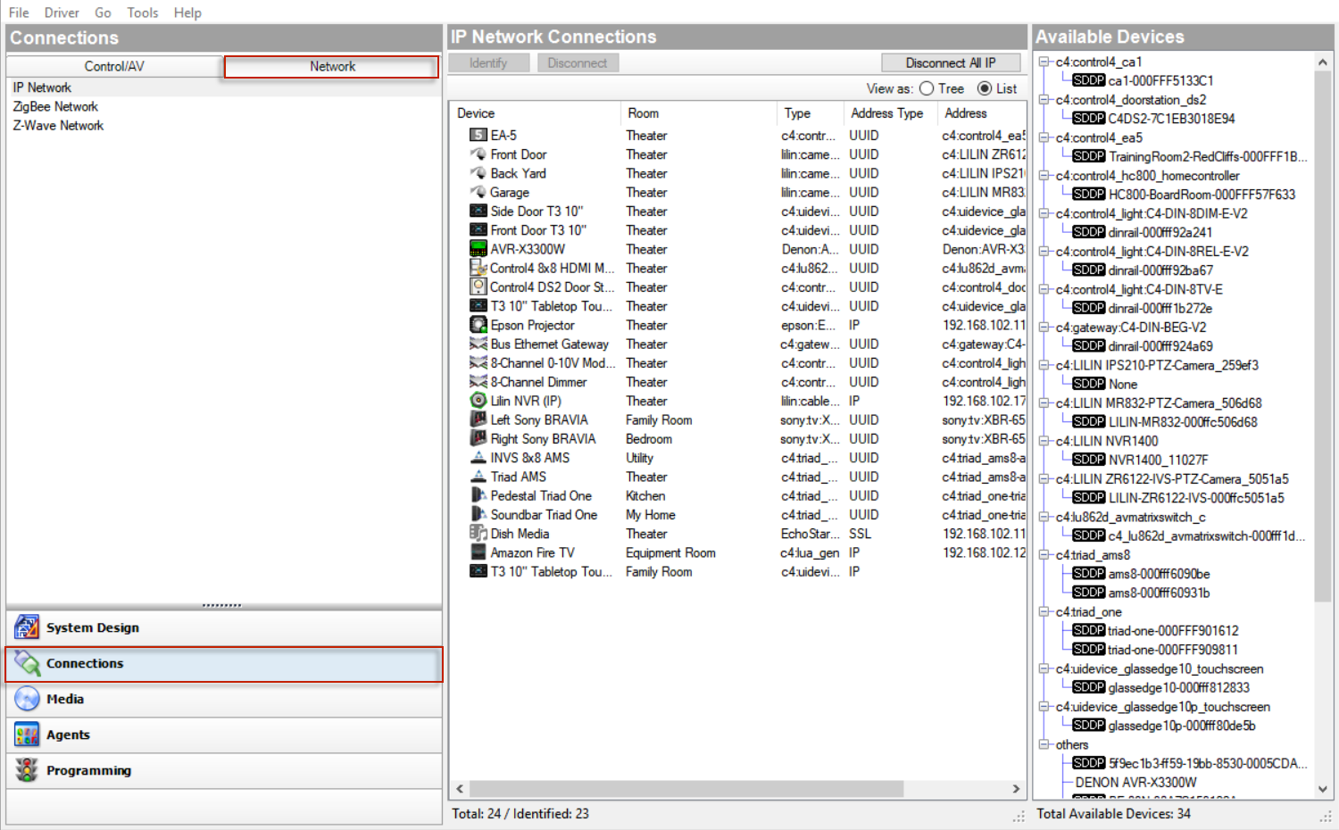
- In Connections, click the Network tab > IP Network (default).
Notice the devices that do not have an address listed in the Address column of the IP Network Connections pane. These devices need to be identified and connected.
Tip: Devices that appear with a highlighted SDDP in the Available Devices pane can be added and identified using Auto Discovery. See “Auto Discovery (SDDP)” in this document for details.
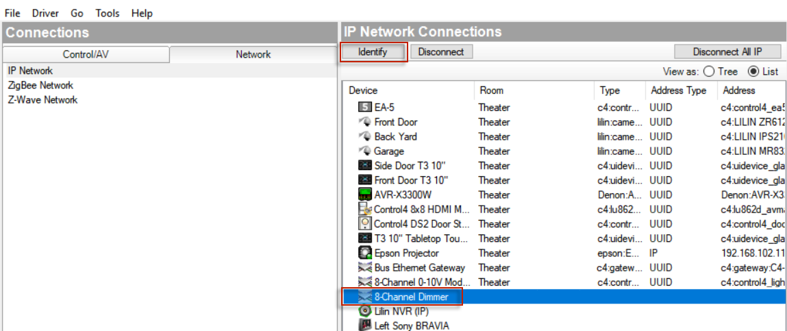
- Select an unidentified device in the address list, then right-click and select Identify (or click the Identify button in the list header). A device-specific instruction screen with a graphic of the device displays (for example, 8 Channel Dimmer).
- At the physical device, press the Identification button or dial, as indicated on the screen. The button to be pushed on the device flashes on the screen.
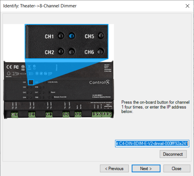
- When the device’s network address displays in the box, click Next to continue, or click Close if you’ve identified the IP network device. Follow these steps for each device.
When you are finished, notice that the Address column is populated with an address for the network device.

- For each device, define the following when applicable:
- Video connections (path of video signals)
- Audio connections (path of audio signals)
- Control connections (how the controller communicates with the device)
To define the connections:
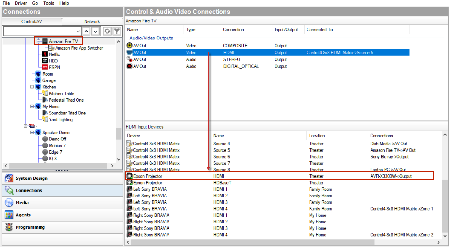
- In Connections, click the Control/AV tab.
- Select a device in the Control/AV tab. The Control & Audio Video Connections for the selected device display in the top pane.
- Select one of the device’s connections in the top pane. The available connections for the selected connection display in the bottom pane.
- To make a connection, drag a device’s input (or output) in the top pane to the output (or input) in the bottom pane.
In the top pane under Audio Video Inputs:
- Click INPUT DVD (Video-COMPOSITE), and drag it to DVD (Output—Theater) in the bottom pane.
- Click INPUT VIDEO 1 (Video-COMPOSITE), and drag it to Home Controller HC-800 (Video Out 1-Theater) in the bottom pane. This connects the Receiver Video 1 input to the controller Video 1 output.
- Click INPUT DVD (Audio-STEREO), and drag it to DVD (Output-Theater) in the bottom pane.
- Click INPUT VIDEO 1 (Audio-STEREO), and drag to Controller (Stereo 1-Theater) in the bottom pane.
- In the top pane under the Control Inputs pane (scroll down), click IR Sensor (Control-IR_OUT), and drag it to Controller (IR Output 2-Theater) in the bottom pane.
Example 2: Make Television Connections
In the top pane under the Audio Video Inputs pane:
- Click AV (Video-COMPOSITE), and drag it to Receiver (Output-Theater) in the bottom pane.
- Click AV (Audio-STEREO), and drag it to Receiver (Output -Theater) in the bottom pane.
- Under Control Inputs, click IR Sensor (Control-IR_OUT), and drag to Controller (IR Output 1-Theater) in the bottom pane.
Example 3: Make module and load connections for Centralized Lighting
In the Control/AV tab:
- Select the room where the module is located, Mechanical Room, and then select the module, for example, 8-Channel Dimmer 1.
- In Control & Audio Video Connections, locate the first entry Channel 1 under Circuit 1.
- Click Channel 1 and drag it to Overhead Lights in the bottom pane.
- Click Channel 2 and drag it to Fan Light in the bottom pane.
- Click Channel 3 and drag it to Alcove Lights in the bottom pane.
- Note ‘Connected To’ in the top pane and ‘Connections’ in the bottom pane. You should see that the module and load are now connected.
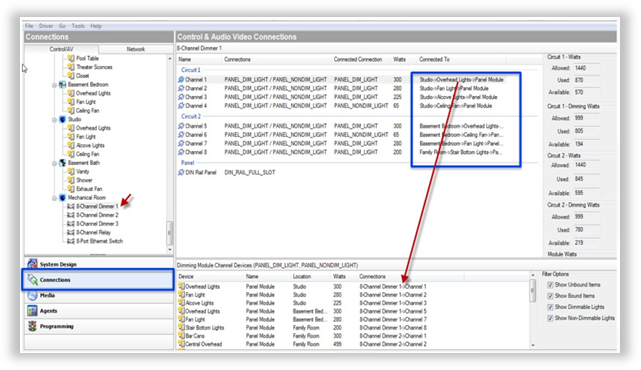
- Filter the loads by Unbound, Bound, Dimmable lights, and Non-Dimmable lights:

- The following example shows bound, non-dimmable lights. This is an easy way to make sure all of your connections are correct.

- View the wattage: max, used, and available wattage for each circuit as you make the connections.
- Circuit watts—The total number of watts allowed on each circuit.
- Dimming watts—The dimming number of watts allowed when using Arc-Fault breakers.
- Module watts—The total number of watts allowed for the module.

Watt types:
- If you get an overloaded circuit error message, connect the load to a different module.

- Connect the modules to the panels.
- It’s easier to connect from the panel to the module.
- Ethernet switches are installed in Slot 5 (bottom slot).
- If 8-channel dimmers are mixed with other module types, the dimmers should be installed toward the top of the panel for the best heat ventilation.
