Configure a Multi-Channel Amplifier
Use the System Design and Connections views to add and configure a Multi-Channel amplifier (C4-16AMP3-B). This device provides eight stereo inputs and outputs with full audio switching.
Note: In Release 1.8 and later, the Multi-Channel amplifier does not work with Zigbee Pro. Configure this device with Ethernet.
Ensure that the Multi-Channel amplifier is installed as directed in the Control4 Multi Channel Amplifier Installation Guide available on the Dealer Portal.
To add and configure a Multi-Channel amplifier:
- To add the driver and identify the device see “How to add devices to a project.” Ensure that the Multi Channel Amplifier v3 - 16 driver is in the project tree.
Note: You can set this device to either DHCP Client (default) or a client that uses Static IP. To change this setting, see the LCD screen menu on the device.
- Make the necessary connections. See “Connect and verify devices” for details.
- (Optional) Change the properties as needed.
- In the System Design view on the project tree, select the Amplifier object.
- Modify the properties in the Properties pane:
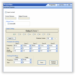
Modifiable properties include:
- Inputs Locked—This locks Audio Inputs to set Audio Outputs. You can have one Audio Input with several Audio Outputs, but an Audio Output may only have one Audio Input.
- Device Firmware—This displays the version of firmware.
- Zigbee Firmware—This displays the version of firmware.
- Volume Curve—Shows how the output volume of the amplifier reacts to an increase in volume; the soft-to-loud response of the volume control.
- Output Settings:
- Output Zones—Select zones 1 through 8.
- Maximum Volume—Use the drop-down menu to select the volume up to 100. Click Set.
- Parametric EQ Settings:
- Frequency—Center frequency to be adjusted.
- Gain—Set from -24dB (cut) to +6dB (boost) for the center frequency.
- Quality Factor (Q)—Width of the EQ boost/cut settable from 0.5 to 1.0 in 0.1 steps and 1.0 to 10.0 in 1 step (there are no units for Q).
- Shelving EQ Settings
- Frequency—Center frequency to be adjusted.
- Gain—Set from -24dB (cut) to +6dB (boost) for the center frequency.
Notes on EQ settings: The Q setting on the EQ setting determines the bandwidth of the boosted frequency (or cut frequency).
The Quality Factor is the center frequency divided by the bandwidth (Q=Center Frequency/Bandwidth), where bandwidth is determined by the frequency points are either side of the center frequency are -3dB from the center frequency. A setting of 1kHz with a Q of 1 means that the boosted frequencies affected are from 500Hz to 1.5kHz (1kHz wide to the -3dB points centered at 1kHz).
Example: If the Q is increased to 10 with the same 1kHz center frequency, then the bandwidth must decrease by the same ratio. Mathematically:
Q = Freq/BW10 = 1kHz/BWBW = 100HzAffected frequencies are Center Frequency +/- ½ (BW)1kHz +/- ½ (100Hz)1kHz +/- 50Hz = 950Hz to 1,050Hz
The higher the Q setting the narrower the frequency range affected by the gain setting, while a lower Q setting increases the frequency range affected by the gain setting at each EQ frequency.
The frequency response can be visualized as a tall, skinny building with a high Q value or a tall, wide (or pyramid shaped) building with a low Q value. The peak (or height of the building) at the center frequency is set by the Gain setting.