Building a project in System Design
Using the System Design view, you create the foundation of the Control4 system by building a project tree in System Design.
Tip: Before you begin to build the system, you may want to assign all of the devices that will be used in the Control4 system unique and meaningful titles if you used a planning worksheet. That way, they will be easy to identify when you connect them to the home network.
To build a new project tree in System Design:
- Start Composer Pro and connect to a Director. A new project opens in the System Design view by default.
- Name—Enter homeowner’s name or other project name.
- Date—Update as needed.
- Time—Update as needed.
- Click to select the project tree.
- Add the locations to the project tree, including sites, buildings, floors, and rooms.
Composer Pro requires this location hierarchy: Site > Building > Floor > Room. The devices will be added to the rooms later.
Tip: You do not have to add every level in the hierarchy manually. If you begin building your project tree by adding a room, Composer Pro automatically adds a Building and Floor object for you. You can easily rename these objects in the tree later.
- In the project tree, select a location (site, building, or floor) where a room exists.
Example: The Master Bedroom is on the Second floor, so you would click Second to select it. Go to the Items pane and double-click or drag-and-drop Master Bedroom to copy it to the project tree.
- In the Items pane > Locations tab, double-click the room you want to add. The room displays in the selected location in the project tree. The room is given a default name, but you can rename it any time by right-clicking on the object in the project tree, and choosing Rename.
- Repeat these steps until you have included all of the floors and rooms on each floor in the home to complete your project.
Example: Add three rooms to the Main floor which already has a few rooms and the Garage.
- Click Theater in the Items pane > Locations tab to add a Home > House > Main > Theater to the project tree.
- Select Main in the project tree, and then click Bedroom to add it to the Main floor.
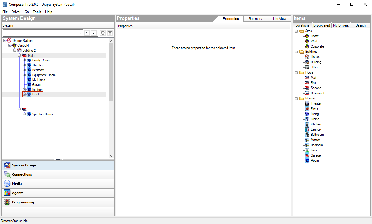
- With Main still highlighted in the project tree, click the Front room to add it to the Main floor.
- Click the room and add the devices. For example, add the controller in a room of the project tree.
Important: Ensure that the devices you select have exact and meaningful titles; for example, “Wireless Dimmer” could be renamed to East Wall Wireless Dimmer for easy recognition later. If you have several devices, such as wireless dimmers, in the same room give them a unique name.
Tip: You can right-click the driver in the project tree to: Rename, Edit Driver, Export Driver, Update Driver, or Delete a driver. Use the same procedure to Update Driver as for Add Driver (see “Driver menu”).
Note: If you installed this version of Composer on a computer that has an older version of Composer, right-click in the white space below the My Driver tab and select Restore Default List. This action updates the My Drivers list.
- Click the room in the project tree.
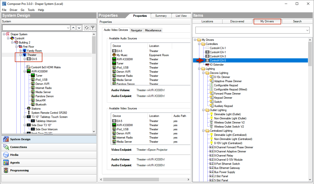
- From Items pane > My Drivers tab, double-click a controller to move it to the selected room (all devices to be added must be selected from the My Drivers tab).
Example: Select the Theater room, and then double-click the controller. The controller and associated Digital Audio objects appear in the project tree. Digital Audio is a component that resides on the controller, but shows up as a separate object in the project tree. Digital Audio provides the functionality to play media.
- Add the Control4 lighting devices and Navigators to the selected room if they reside there.
Example: Add the following devices to the Theater room.
- Double-click Wireless Dimmer, and then rename it to Dimmer.
- Double-click Wireless Switch, and then rename it to Light Switch.
- Double-click Wireless Outlet Switch, and then rename it to TV Outlet Switch. (This will be used to control the power on a TV that uses an On/Off toggle switch.)
- Double-click System Remote Control SR-250.
- Double-click 6 Button Keypad.
Note: If you have a wireless touch screen, add it now to your project.
- Add all applicable audio and video devices to the selected room.
- Select the Theater room in the project tree.
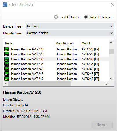
- Double-click Receiver in the Audio/Video section of the My Drivers tab. A dialog box displays with Local Database selected and the receiver drivers that are currently available in the local database.
- Select the receiver’s manufacturer and model. In the dialog box, select Online Database, select the manufacturer Harmon Kardon, and then double-click AVR230[IR].
- Select the Theater room in the project tree.
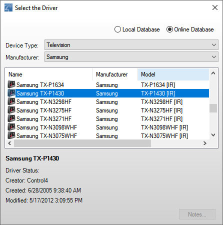
- Double-click Television in the Audio/Video section of the My Drivers tab. A dialog box displays with local database selected, and the TV drivers currently available in the local database.
- In the dialog box, select Online Database, select the manufacturer Samsung, and then double-click TX-P1430[IR].
- Select the Theater room in the project tree.
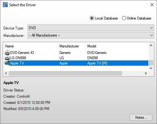
- Double-click DVD in the Audio/Video section of My Drivers tab.
- In the dialog box that appears, select Online Database, select the manufacturer Apple, and then double-click DVD Apple TV [IR].
Here are three examples to follow.
Example 1: Add a receiver to the Theater room
Note: The Receiver object is added to the tree, along with a Tuner. The next time you add a receiver to this project, the AVR230[IR] will appear in local database driver list.
Example 2: Add a TV to the Theater room
Notes:
The UHF/VHF object is added automatically to enable you to scan for UHF/VHF broadcast channels.
The next time you add a TV to this project, the TX-P1430[IR] appears in the local database driver list.
Example 3: Add the DVD player to the Theater room
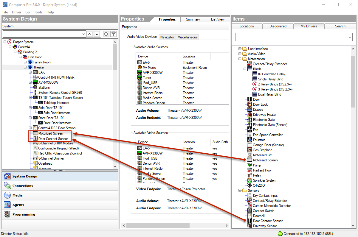
- Add Motorized devices or Sensors, if applicable, to the selected room.
Example: From the My Drivers tab, add a Motorized Screen and a Door Contact Sensor to the Theater room from the online database.
- Select Theater in the project tree.
- In the My Drivers tab under Motorization (scroll down), double-click Motorized Screen.
- In the My Drivers tab under Sensors (scroll down), double-click Door Contact Sensor.
- Add an HVAC, if available, to the selected room.
- Add a Security Panel, if available, to the selected room.
- Add an IP Camera, if available, to the selected room.
- Add a pool and spa controller, if available, to the selected room.
- Add Network File Storage, if available, to the selected room.
- Repeat Steps 6–8 as needed for each room.
- Identify and the test the connections. See the Composer Pro User Guide for configuration and connection information.