Connections view
Use the Connections view to define to the Control4 system the physical connections and addresses of each device added to the Control4 system. The connections are added automatically when you add the device, but you need to connect each device to other devices in the system. See the Composer Pro User Guide for details.
To access the Connections view:
- Click Connections at the bottom of the left pane (see orange highlight).
- Categories:
- Columns:
- Name—The name of the connection
- Type—The connection category, for example, Audio or RoomControl
- Connection—The connection type, for example, HDMI or Component.
- Input/Output—Shows whether the connection is for input or output.
- Connected To—Shows which device this connection is connected to.
- Device—The name of the device.
- Name—The name of the connection on the device.
- Location—The room where the device is located in the project tree.
- Connections—Lists the devices connected to this connection.
The Connections pane (left side) has two tabs:
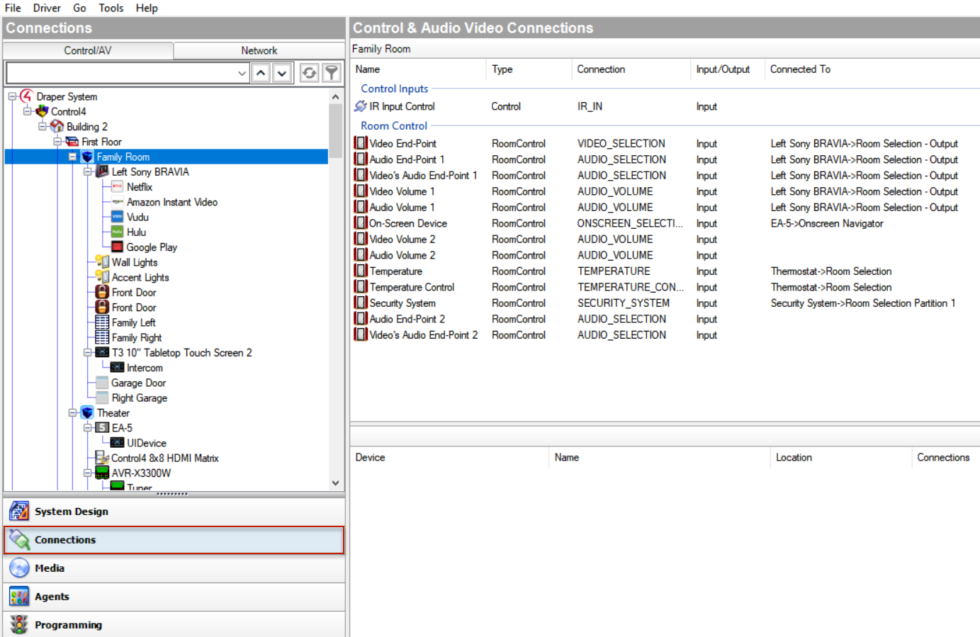
The Control & Audio Video Connections pane has three categories and several columns:
The bottom pane has several columns:
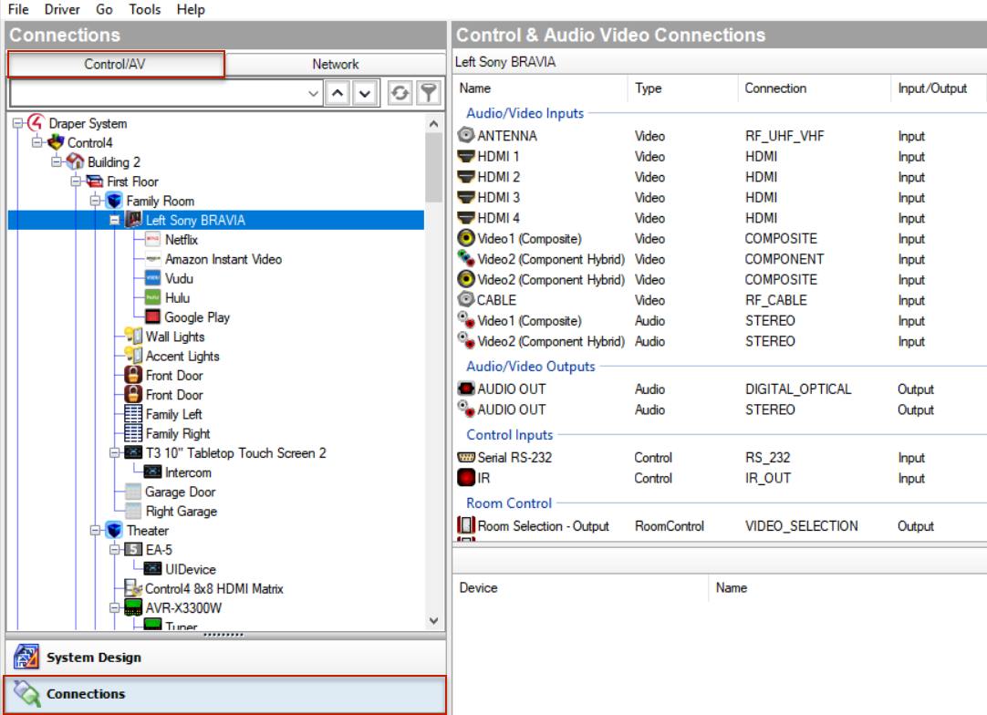
Control/AV tab
Use the Control/AV tab in the Connections view to define the physical connections between the Control4 controller and other devices you add to the Control4 system, including AV signals, IRs, relays, contacts, and/or serial connections.
To access the Control/AV tab:
- Click Connections at the bottom of the left pane.
- In the Connections pane, click the Control/AV tab.
- The left pane displays the project tree.
- The right pane lists the actual device connections.
- If you click an object in the project tree of the Control/AV tab, you are selecting either a room or a device to display the following types of connections in the Control & Audio Video Connections pane:
- Room Connections—Lets you define the connections specific to the room which can include, for example, a thermostat that you can control from a touch screen, Control4 app, or on-screen Navigator. Room connections help you customize and design the devices to perform specific functions in the room.
- Control & Audio Video Connections—If you select a device in the Connections > Control/AV tab, the available Control & Audio Video Connections pane displays the following panes:
- Available inputs and outputs—The top pane identifies the available inputs and outputs of a device to make its connections.
- Connected items—When you select an item in the top pane, the bottom pane displays the available connections for that input or output.
- To make the actual connection, select the item in the top pane, and drag it to the associated item in the bottom pane.
- Audio/Video Inputs—Shows the available audio and video inputs. In this category, the video connections are listed first, and then the audio connections.
- Audio/Video Outputs—Shows the available audio and video outputs. In this category, the video connections are listed first, and then the audio connections.
The Control/AV tab contains two panes:
If you select a room (for example, Family) on the Control/AV tab, the available room connections appear in the pane under Family (the bar just below Control & Audio Video Connections). The Video, Audio, or Video’s Audio End-Points and the Audio or Video Volume are all defined for the room.
Note: If you select a device on the project tree and nothing appears, the device doesn’t have any control or AV connections; maybe it uses the network connection to communicate to the controller. In these cases, use the Network tab to identify this device’s network address to the system. See “Network Tab” below.
The available input and output categories for the selected device display in this order:
If the connections you need do not appear, you can edit the driver to create the needed connections. From the Driver menu (in the Composer menu bar), select Edit Existing Driver to open the Driver Wizard.
Note: Editing drivers is an advanced task and is out of the scope of this document. Details about the Driver Wizard are discussed in the Composer Pro User Guide or you can use the Driver Editor. Talk to your Control4 Sales Representative to find out how to order this tool.
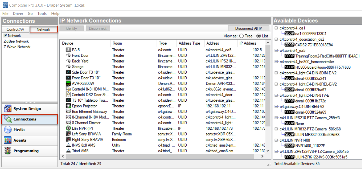
Network tab
Use the Network tab in the Connections view to display a list of all devices in the system that have a network connection and use a network address. Click the Identify button (for releases older than OS 2.2 or to re-identify a device) to establish the network connection for any device that communicates to the controller using TCP/IP, Wi-Fi, Zigbee, or any other device that uses a network address.
To access the Network tab:
- Click Connections at the bottom of the System Design pane.
- In the Connections pane, click the Network tab. The Network tab displays the network type, for example, IP Network, along with the
- IP Network Connections pane, and the
- Available Devices pane.
The IP Network Connections pane lists all devices for the selected network type. After identifying the network connection, the device’s address appears in the IP Network Connections pane under Address.
- Buttons
- Identify—Select a device from the IP Network Connections pane and click Identify to have Composer identify the device. This causes Director to listen on the network for the device to broadcast its network address, Zigbee address, or network name. Once Director is waiting for the device to identify itself, you must cause the device to broadcast its address on the network. The Identify window gives a description on how to make a device identify itself.
- Disconnect—Select the device, and then click Disconnect to remove the connection.
- Disconnect All—Click Disconnect All to remove all of the connections.
- Columns
- Device—The name of the device.
- Room—The room in which the device resides.
- Type—The device type recognized by the system.
- Address Type—The type of address used, for example, Zigbee.
- Address—The deviceaddress.
After identifying the network connection, the device address appears. If a device does not have an address next to it, it needs to be identified to the system.
The Available Devices pane shows the list of devices that the network has discovered. Each device shows up under the service type. It also displays the total number of devices found and the number of connected or unconnected devices of each type.
Tip: Throughout the Control4 system, devices are identified using various types of addresses, for example, Zigbee, Zigbee Pro, IP, UDP, etc. These types of addresses are known as “network addresses.”