Web UI Control
The Web UI designed for the matrix is available for basic controls and advanced settings of the device. The Web UI can be accessed through a browser. The matrix’s default network mode is DHCP. If there’s not a DHCP server, the matrix supports a local 169.254.xxx.xxx IP address.
To gain access to the web UI, perform the following steps:
-
Connect the LAN port of the matrix to your PC using a straight UTP cable or connect the matrix to a local area network and connect your PC to the same network. Using the latter connection, ensure a DHCP server is included in the local area network.
-
Use a tool, such as OvrC, to search the IP address of the device or send API command to get the IP address (For more information, see the separate document “API Command Set_B-660- MTRX-8x8”). If the matrix is connected directly to your PC, set your PC to the same network segment as the matrix.
-
Input the IP address in your browser and press Enter. The following window will display.
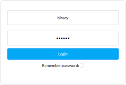
Enter the username and password. The default username and password are both “binary”. Then, click Login. Upon the first login, the following page will appear to prompt you to change the username and password.
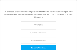
Note: -__.The changed username and password must be different from the default username and password.
Note: -__.Username and password must be 4 to 16 characters in length, alphanumeric only.
Web UI Introduction
The web UI page includes the following sub-menus: SIGN OUT, FACTORY DEFAULT, UPDATE and REBOOT in the upper-right corner, Matrix Control, Log and System in the main page.
Sign Out

Click this button to return to the login page.
Factory Default

Click this icon, then click CONFIRM to reset the device to factory default.
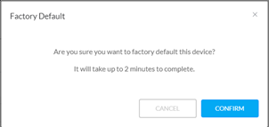
Note: -__.Please wait three minutes to refresh the web page and log in again.
Update

Click this icon to update the system’s firmware.
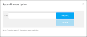
Click BROWSE to select the .zip update file, and then click UPDATE to start the firmware update.
Note: -__.Do not power off the device while firmware update is in process.
Reboot

Click the Reboot icon, then click CONFIRM to reboot the device.
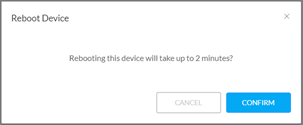
Note: -__.Please wait at least 2 minutes to refresh the web page and log in again.
Matrix Control
Move the mouse over Matrix Control in the web UI, it shows the following sub-menus: Switch and preset, Configuration and Display control. Click the item you want to configure.
Switch and Preset
Video Control
This section manages distribution of input video sources to output displays. Click the button in the table to select the input for the output display (button turns from white to blue once selection is done).
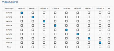
All Outputs: Click to route one input to all outputs.
None: None input is routed to the output (or the output is turned off).
By default, video Input 1 routes to Output 1, Input 2 routes to Output 2, etc.
Audio Control
This section allows you to select audio source for each audio output.
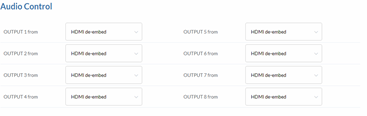
HDMI de-embed: AUDIO OUT port outputs de-embedded audio from the corresponding HDMI OUT port.
HDMI ARC: AUDIO OUT port outputs ARC audio from the corresponding HDMI OUT port.
The default setting for each audio output is: HDMI de-embed.
Presets
This section saves/loads the input/output switch settings to or from the Matrix.
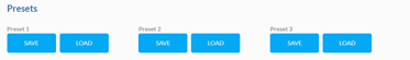
SAVE: Settings in Video Matrix Control section are saved.
LOAD: Preset already saved is loaded.
Configuration
This section allows you to rename each input and output, set EDID for each input, and show video and audio information for inputs and outputs.

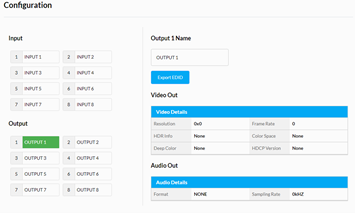
Input/Output: Select one input/output to set and show its video and audio information.
Input Name/Output Name: Change the input/output names.
For Input:
EDID: Click to select the EDID for input.
Apply: Click to make the EDID setting take effect.
Export EDID: Click to save the EDID information of the selected input port as a bin file to local PC.
Video In/Audio In: Show the video and audio information for selected inputs.
For Output:
Export EDID: Click to save the EDID information of the TV connected to the selected output port as a bin file to local PC.
Video Out/Audio Out: Show the video and audio information for selected outputs.
Display Control
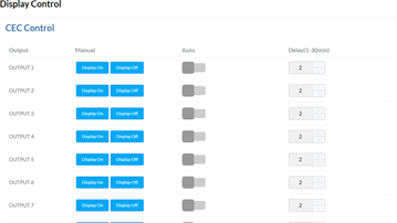
Display On: Click to send the saved Display On command to the connected CEC-enabled display to power on it immediately.
Display Off: Click to send the saved Display Off command to the connected CEC-enabled display to power off it immediately.
Auto On/Off: Click to enable or disable the CEC Auto Control. By default, the auto CEC control is on.
Delay Time (1-30 min): Click the up/down arrow to set the time for the display to power off automatically when no signal is present. For example, if Auto control is set as on and the time is set to 2 minutes, the output display will power off automatically when there’s no signal at the display for 2 minutes.
Log
API Test
This section allows you to input API commands to control the matrix.
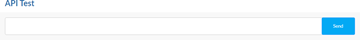
Send: Click to send the entered command to the matrix.
Note: -__.For more API commands, please refer to the separate document “API Command Set_B-660- MTRX-8x8”.
The return information of the sent command will be shown in log box:
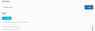
Log
This section shows the operation log and return information of the tested command.

Export Log: Click to export omni log recording information for remote troubleshooting.
System
Move the mouse to “System” in the page, it shows the following sub-menus: Information, Network and Other. Click the item you want to configure.
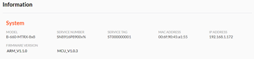
Information
This section shows the basic information of the matrix, including MODEL, SERVICE NUMBER, SERVICE TAG, MAC ADDRESS, IP ADDRESS and FIRMWARE VERSION.
Network
Network is used to set between the static and dynamic IP address.
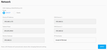
DHCP: When enabled, the IP address of the Matrix is assigned automatically by the DHCP server connected.
Static: When enabled, set up the IP address manually.
Apply: Click to enable the network setting.
Note: -__.When Static is selected, please ensure your PC is in the same network segment as the Matrix. The IP address of your PC should be set to 192.168.xxx.xxx.
Note: -__.Please wait for two to three minutes for the Matrix’s LAN module to reboot and reconnect after the network setting is changed.
By default, the IP type is set to DHCP. If it doesn’t have a DHCP server, the matrix supports a local IP address. Use API Command to obtain the IP address.
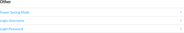
Other
The Other section contains settings for Power Saving Mode, Login Username, and Login Password. These are described below.
Power Saving Mode
This section allows you to turn Power Saving Mode on or off. The default setting is Off.
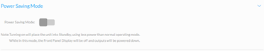
Note: -__.When Power Saving Mode is set to On, the matrix enters standby mode to use less power than normal operation mode. In this mode, the front panel display will be off and outputs will the powered down.
Login Username
This section allows you to change the username.
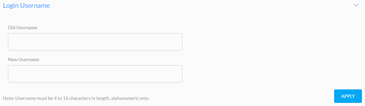
Apply: Click to apply the new username.
Note: -__.Username must be 4 to 16 alphanumeric characters in length.
Login Password
This section allows you to change the password.
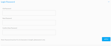
Apply: Click to apply the new password.
Note: -__.Password must be 4 to 16 alphanumeric characters in length.